

Wiring diagrams for open (top) and closed (bottom) switches. When a switch is open, electricity is not able to flow through. When closed, electricity can travel across the switch. The switches in our lab are normally-open, so you have to press them to close the circuit.
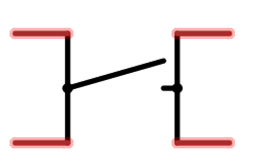
In our lab schematics, switches are shown like this. Notice how there are two pins per side of the switch that are connected together on the inside. This means that compnents connected either side of the switch are connected together by the switch but compnents across are only connected when the switch is closed.
Wiring diagrams for open (top) and closed (bottom) switches. When a switch is open, electricity is not able to flow through. When closed, electricity can travel across the switch. The switches in our lab are normally-open, so you have to press them to close the circuit.
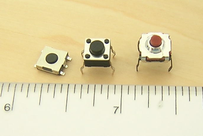
To wire a tactile switch to an Arduino, there are two methods:
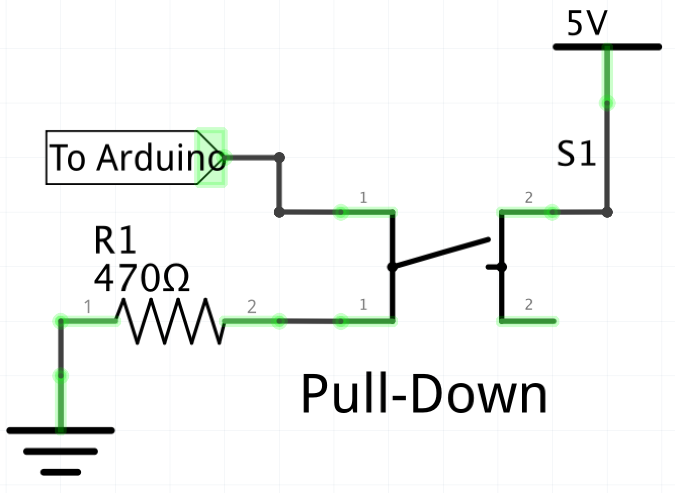
The idea behind this method is, when the switch is closed, the pin on the Arduino is set to +5V, when the switch is open, the pin on the Arduino is GND. This represents a 1 in binary inside the Arduino, and therefor the code should be written to get the Arduino to do something when the input is 1.
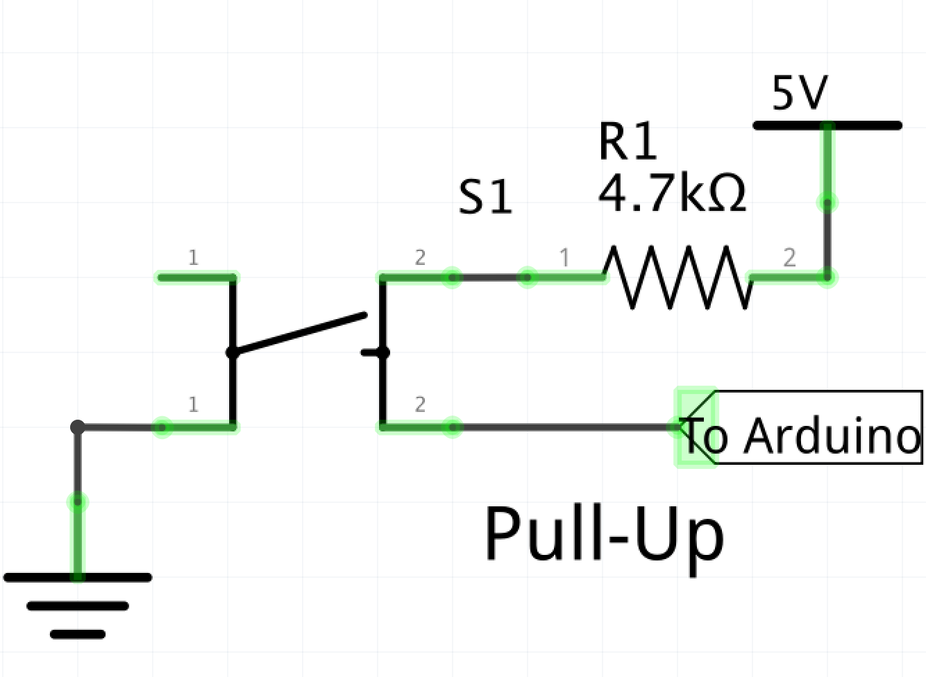
This is the method we'll be using in the labs. When the switch is closed, it is brought to GND, when the switch is open, it is +5V. The Arduino should be coded to do something when it receives a 0 instead of a 1.
: sparkfun.com - Switch Basics
: ElectronicsTutorials.com - Pull-up Resistors
Images on this page from: Wikipedia.org